Why Plenoptic Imaging?
Imaging underwater is notoriously difficult.

Colour-dependent attenuation, backscatter, light columns and caustics, suspended particulate matter and other dynamic distractors, and distortion effects at the underwater viewport all complicate effective underwater imaging.
In contrast with typical terrestrial robotic applications, the underwater environment also tends to be unstructured, lacking the straight edges and right-angled corners typical of man-made environments, and displaying a high degree of self-similarity — one small patch of coral looks very much like hundreds of other small patches of coral, over multiple scales.
In the case of imaging from an AUV, the underwater imaging platform presents further limitations: power budgets limit the amount of illumination that can be practically provided, and hardware limitations restrict frame rates to at most a few frames per second. Optics at the underwater viewport and illumination constraints limit the field of view to about 45 degrees, and light attenuation limits the imaging range to 2-3 metres.

An AUV is in constant motion, and so long exposure times lead to motion blur. This effect is exacerbated in higher-resolution sensors, for which less motion is required to observe a blurring effect, effectively limiting the resolution of imagery that can be practically gathered from an AUV.
Plenoptic imaging promises solutions to many of these problems. Since 2010 the Marine Robotics group at the ACFR has been exploring the possibilities presented by plenoptic imaging in the underwater environment.
Though motivated by the challenges of underwater imaging, much of this work has applications beyond the underwater domain.
What is Plenoptic Imaging?
Plenoptic imaging has been around for more than 100 years, and has appeared under many forms and names: integral photography, light field cameras, generalised cameras, and polydioptric cameras to name a few. Plenoptic imaging is a form of computational photography, in that the camera gathers richer information than a conventional camera, then applies computational approaches to render from that rich data.
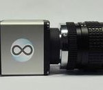
An intuitively pleasing way to construct a light field camera is by assembling an array of conventional, monocular cameras. This was the approach taken at Stanford in constructing their Multi-Camera Array.
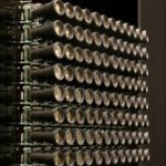
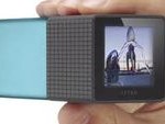
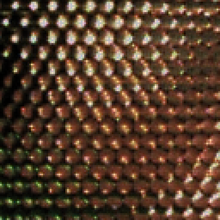
Less obvious but arguably more useful, the same form of information can be measured by introducing a lenslet array into the optical path of a monocular camera, as in the commercially-available Lytro and Raytrix cameras.
Some of our research is outlined below, and explored in more detail in:
D. G. Dansereau, “Plenoptic signal processing for robust vision in field robotics,” Ph.D. dissertation, Australian Centre for Field Robotics, School of Aerospace, Mechanical and Mechatronic Engineering, The University of Sydney, Jan. 2014. Available here.
Decoding, Calibration and Rectification for Lenslet-Based Cameras
The Downloads section, below, includes a toolbox for decoding, calibrating and rectifying images from the Lytro light field camera; future releases are slated to include filtering and additional input formats.
A prime concern in applying plenoptic cameras to tasks in machine vision and robotics is calibration. A conventional approach is to calibrate all plenoptic cameras as though they were arrays of monocular cameras. In the case of lenslet-based cameras, we have demonstrated that a superior approach is to directly model the optics of the camera. The resulting model is of much lower dimensionality than camera array models, and more closely represents the physics of lenslet-based cameras.

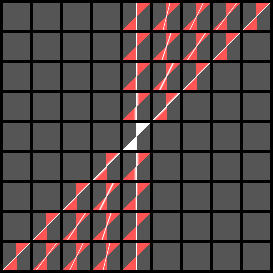
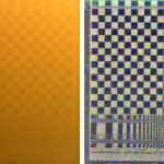
Before one can calibrate a lenslet-based light field camera, its imagery needs to be decoded — transformed from a 2D grid of lenslet images into a 4D array. We have developed a conceptually simple way of doing this involving an affine transformation which aligns the lenslet images to a regularly sampled grid.
Refer to our CVPR 2013 paper for a detailed description of this work:
D. G. Dansereau, O. Pizarro, and S. B. Williams, “Decoding, calibration and rectification for lenselet-based plenoptic cameras,” in Computer Vision and Pattern Recognition (CVPR), IEEE Conference on. IEEE, Jun 2013. Available here.
Low-Contrast Imaging / Image Denoising / Volumetric Focus

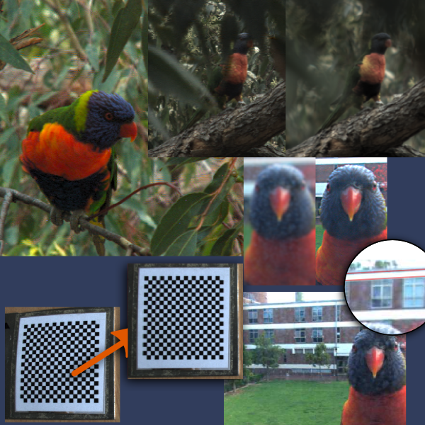
Low light and murky water are common issues in underwater imaging. Ground-based and flying vehicles face similar problems when operating at night or in snow, rain, fog or dust. Plenoptic cameras offer two ways of mitigating these issues: first, contrary to a common misconception, plenoptic cameras gather significantly more light than conventional cameras for a given depth of field, helping them see well in the dark; secondly, they offer depth selectivity, allowing foreground particulate matter and other distractors to be significantly attenuated.
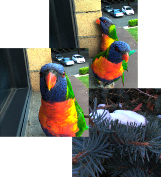
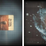
In our 2013 work we demonstrate a single linear filter that passes a prescribed range of depths in a scene, selectively enhancing the desired signal while rejecting noise and distractors such as dust and particulate matter. The process is closely related to focussing, except we maintain sharp focus over a range of depths, not just on a single plane.
This builds on previous work in which single depth is put in focus by selectively filtering a plane in the frequency-domain. This was shown in 2003 in the paper:
D. G. Dansereau and L. T. Bruton, “A 4D frequency-planar IIR filter and its application to light field processing,” in Proceedings of the Intl. Symposium on Circuits and Systems, vol. 4, May 2003, pp. 476–479. Available here.
and again in a 2005 paper by the group that would later go on to found Refocus Imaging, which relaunched as Lytro:
Ng, Ren. “Fourier slice photography.” In ACM Transactions on Graphics (TOG), vol. 24, no. 3, pp. 735-744. ACM, 2005.
Related follow-on work has dealt with ranges of depths either through iterative layering or by using separable 2D filters. We have shown that the same effect can be accomplished with a single linear filter having a truncated hypercone-shaped passband, which we call a hyperfan. The frequency-domain hyperfan is irreducibly four-dimensional, and we have demonstrated that previously-described 2D filters yield significantly lower performance.


Check out some more light field filtering examples here.
The hyperfan filter is similar to planar focus in that it combines light coming from different directions, helping to reject noise, but it does so over a range of depths. Please refer to our SPIE 2013 paper for further information:
D. G. Dansereau, D. L. Bongiorno, O. Pizarro, and S. B. Williams, “Light field image denoising using a linear 4D frequency-hyperfan all-in-focus filter,” in Proceedings SPIE Computational Imaging XI, Feb 2013. Available here.
Distractor Isolation

This work explores the use of spatio-temporal light field filtering to isolate moving scene elements. In our 2011 paper we show how a sequence of frames measured by a dynamic AUV can be filtered for static or dynamic scene elements using a single 3D linear fan filter.
The difficulty in this application arises from the motion of the camera and the 3D structure of the scene:everything appears to be moving as far as the camera is concerned, so a useful approach needs to take parallax motion within the scene into account. We demonstrated that simple linear filters, in this case a 3D spatio-temporal fan filter or its inverse, effectively address this problem.
D. G. Dansereau and S. B. Williams, “Seabed modeling and distractor extraction for mobile AUVs using light field filtering,” in Robotics and Automation (ICRA), IEEE Intl. Conference on. IEEE, May 2011, pp. 1634–1639. Available here
Plenoptic Flow: Visual Odometry
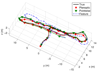
This work generalizes 2D optical flow to allow closed-form visual odometry in full 3D space — i.e. with 6 degrees of freedom (DOF). An optical mouse uses a 2D image sensor and a system of 2 equations to build a closed-form solution for its 2D motion in a plane. We have demonstrated how 4D light field imagery can used to build a system of 6 equations to solve for 6-DOF motion in 3D space. We call this method Plenoptic Flow.
Because the solution is closed-form, it is fast, has a constant runtime, and is appropriate for implementation in embedded systems. Because all measured information is used, robustness to noise is higher than feature-tracking methods.
D. G. Dansereau, I. Mahon, O. Pizarro, and S. B. Williams, “Plenoptic flow: Closed-form visual odometry for light field cameras,” in Intelligent Robots and Systems (IROS), IEEE/RSJ Intl. Conf. on. IEEE, Sept 2011, pp. 4455–4462. Available here
Downloads
The Matlab Light Field Toolbox v0.4 released 12-Feb-2015
Available for download here http://www.mathworks.com/matlabcentral/fileexchange/49683.
This is a set of tools for working with light field (aka plenoptic) imagery in Matlab. Features include decoding, calibration, rectification, colour correction, basic filtering and visualization of light field images. New in version 0.4 are some linear depth/focus and denoising filters.
Download the sample light field pack at http://www-personal.acfr.usyd.edu.au/ddan1654/LFToolbox0.3_Samples1.zip.
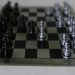
The Lego Knights, Chess and Tarot light fields are available at the Stanford Light Field Archive
Small Sample Calibration
This small example is intended as a fast test to validate the calibration code, and does not represent a very good calibration dataset. See some of the larger datasets, below, for better examples. The small sample calibration is available here:
CVPR 2013 Plenoptic Calibration Datasets
These are the five datasets used in our 2013 CVPR paper on decoding, calibration and rectification. Datasets A and B are good example datasets for calibrating a Lytro-like camera, in that they feature dense grids imaged at close range and over a diverse variety of poses.
- http://www-personal.acfr.usyd.edu.au/ddan1654/PlenCalCVPR2013DatasetA.zip
- http://www-personal.acfr.usyd.edu.au/ddan1654/PlenCalCVPR2013DatasetB.zip
- http://www-personal.acfr.usyd.edu.au/ddan1654/PlenCalCVPR2013DatasetC.zip
- http://www-personal.acfr.usyd.edu.au/ddan1654/PlenCalCVPR2013DatasetD.zip
- http://www-personal.acfr.usyd.edu.au/ddan1654/PlenCalCVPR2013DatasetE.zip
Deprecated
The Matlab Light Field Toolbox v0.3 released 10-Nov-2014: http://www.mathworks.com/matlabcentral/fileexchange/48405.
The Matlab Light Field Toolbox v0.2 released 27-May-2013: http://www.mathworks.com/matlabcentral/fileexchange/41511.
The original sample packs 1 and 2, these are all included in the new sample pack above: http://www-personal.acfr.usyd.edu.au/ddan1654/LFSamplePack1-r2.zip and http://www-personal.acfr.usyd.edu.au/ddan1654/LFSamplePack2.zip